
Beamline Description
|
In order to fulfill the required flexibility in terms of beam characteristics at the experiment, ranging from spot focus to line focus and to parallel beam, the optics of the line consist of two mirrors and the monochromator: a first Pt-coated cylindrical mirror collimates the beam on the horizontally focusing Si (111) double crystal monochomator in 1:1 configuration. The second - vertical focusing - platinum coated mirror is flat and bendable, with a radius adjustable from 6 km to flat. The double crystal monochromator (DCM) consists of two Si crystals (active area 50×50 mm2, manufactured cut along the [111] direction, which can be precisely positioned and oriented in the X-ray beam. Two successive Bragg reflections with an inherent energy resolution of 0.014% (given by the Darwin angular width of the Si 111 reflection) will direct photons of the desired energy parallel to the incoming beam direction, but offset upward (out of the direct Bremsstrahlung beam). This "fixed exit" operation is achieved by placing the crystals on two independent rotation stages, and translating crystal 2 along the beam direction. The second crystal provides sagittal focusing; it is a ribbed crystal, cylindrically bent to a variable curvature radius. |
 Fig.1 - Schematic of the Materials Science Beamline optical system, showing, from left to right, the first (vertical collimating) mirror, the first (flat) crystal, the second (horizontal focusing) crystal and the second (vertical focusing) mirror. |
The MCX beamline has two endstations.
 |
 |
Diffractometer
|
The station has been designed to provide the maximum flexibility and easy use with reasonable precision and performance and is based on a 4-circle Huber goniometer (2θ precision better than 0.0001°) in full circle configuration with a flat sample-holder plate (Ø 100 mm) controlled by a precision (1 m) x-y-z motor system, 360° phi-rotation and -90 ÷ +90° chi-tilting. The 2theta rotation is provided with a shaft optical encoding system for accurate control and real-time feedback on the actual angular positions. The diffracted arm carries, as a default, a crystal analyser/scintillation detector system. Changes in photon energy will require a (remote-controlled) realignment of these components. Provision will be made for later extension of the analyzer-detector system to a multi-analyser-detector system. A second detector system will be based on a photo-diode counter, for high counting rates operating mode (e.g., in reflectivity measurements, single crystal studies, epitaxial layers). Remote control attenuators, placed before the diffractometer, are used to automatically reduce the incoming beam intensity, adapting it to the time characteristics of the detectors. In addition to the flat-plate mounting, capillary measurements are possible with a simple spinner tool installed on the sample-holder. Provision of a removable He-enclosure allowing data collection at low energy is also foreseen. In addition chambers can be mounted on the standard sample-holder plate, for specific atmosphere control and reactive (kinetic) studies. Special attachments to be installed on request will include mechanical testing machines (4-point bending and tensile testing) as well as a high temperature stage. The whole system is controlled by means of in house developed software, which also provedes an easy to ise graphical interface and associated macro sets for data acquisition. |
|

Furnace
|
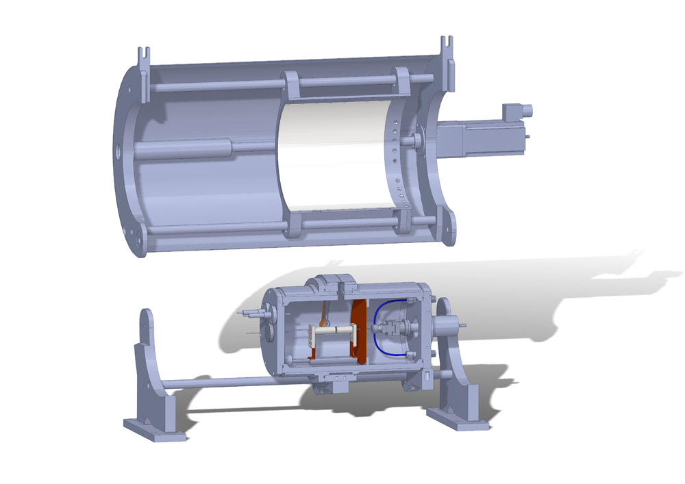
The furnace provides an atmosphere and temperature controlled environment for powders in capillaries and a temperature controlled environment for thin-film samples. The diffraction patterns are collected on a translating image plate (IP). The furnace is composed of two parts (see fig:1): i) The main cylindricalvacuum chamber divided by a thermal barrier (i.e. a cupper diaphragm) into a hot room where the heating element is placed and a cold room hosting the sample alignment stage and gas-flow system. The hot room has a aperture for thge incoming beam and a slot on its circumference for the diffracted signal. ii) The translating detector system constituted where the imaging plate is placed over a magnetic support. The furnace is on a motorizedd table designed to allow a quick alignment with the incoming beam.
The heating element in the hot room consosts in a resistive filament wrapped around an alumina tube. A k-type thermocouple positioned in the proximity of the sample monitors the temperature feeding back the information to the PID controller. Control software allows to synchronize opening and closing of the shutter, the translation of the imaging plate and the desired temperature conditions (heating ramp, isothermal transformations, radiative cooling...). |
|
Last Updated on Thursday, 04 August 2022 15:41
